 Skip to content
 ")
What Is 3D Vision-guided in industrial painting ?
On large-panel automated painting lines, People usually use a dynamic 3D vision system to track workpieces in real time, guiding robots for trajectory-based spraying. Panels of different shapes can be dynamically recognized to fit the complete contour.
- The 3D vision system scans and locates the workpiece, providing position deviation data on the conveyor, enabling the robot to start spraying in the correct pose according to the process design.
- For panels with simple shapes and low-complexity trajectories, the system already meets positioning requirements.
- If needed, it can also perform spray path planning while locating, further improving robot productivity.
___________________________________________________________________________________
Why Is 3D Vision-guided Critical in Automated Spray Painting?
Factories face constant changes in part shapes, batch sizes, and surface complexities. This technology addresses critical challenges in industrial automated spray painting:
- Precision Coating: Ensures uniform paint application and minimizes overspray.
- Flexibility: Adapts to part variations without lengthy reprogramming.
- Cost Efficiency: Reduces paint waste, labor costs, and rework.
- Workplace Safety: Minimizes human exposure to hazardous environments.
- Sustainability: Optimizes material use for eco-friendly operations.
For industries embracing smart manufacturing, this solution ensures competitiveness and long-term resilience.
___________________________________________________________________________________
Vi-LiDAR : 3D Vision-Guided System in Operation
Case Study : Chanllenges from LB Technology in automated spray painting
In automated spray painting, precise positioning of trolleys has long been a hidden bottleneck. LB Technology Company faced three core issues:
1. Inefficient Operations and Safety Risks
Traditional methods relied on manual measurement: Operators wore protective gear to calibrate distances/angles repeatedly.
- Manual measurement consumed significant time per part.
- Prolonged exposure to paint fumes and chemicals led to significantly higher occupational health risks compared to industry norms.
2. Non-Standardized Coating and Waste
Human error caused uneven paint thickness (runs or bare spots). A client case revealed:
- A 10% distance deviation increased paint waste by massive percentages, costing millions annually.
3.Inflexible Production Lines
Multi-variety, small-batch production required lengthy downtimes for part changes. One NEV manufacturer faced significant annual losses due to inefficient production workflows.
___________________________________________________________________________
VI-LIDAR’s 3D Vision-Guided Solution for LB Technology
Vi-LiDAR’s dynamic pre-alignment system achieves centimeter-level precision through a “detect-feedback-correct” closed loop:
Static Alignment Mode (Millimeter-Level Initialization)
- Step 1: 3D Scanning – LiDAR generates sub-centimeter point-cloud models of workpiece surfaces.
- Step 2: Pose Calculation – AI algorithms compute deviations between workpiece coordinates and spray trajectories.
- Step 3: Servo Correction – PLC-controlled trolley movements ensure initial pose errors stay within ±1mm.
During pre-spray adjustments, the system outputs yaw angle (±0.5°) and normal distance (<1cm) updates at 10Hz. Temperature compensation algorithms adapt to ±40°C environmental fluctuations.
Vi-LiDAR : 3D scanning workpiece demo
Process Workflow (Closed Loop)
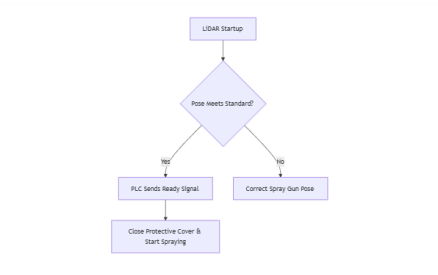
- Step 1: Scanning – LiDAR scans and calculates pose in real time.
- Step 2: Adjusts angles – PLC adjusts trolley angles (<0.5°) and distances (<1cm).
- Step 3: Servo Correction – System signals “Ready” upon pose validation.
- Step 4: Safety protocols engage – Scan shutdown, protective cover closure, or data output halt.
- Step 5: Quality monitoring – Vision feedback ensures consistent thickness and finish.
This closed-loop approach makes vision-guided spraying far more precise than fixed-path robotic systems.
______________________________________________________________
Benefits of 3D Vision–Guided solution
- Enhanced Coating Quality: Reduces defects and ensures uniformity.
- Material Savings: Optimizes spray angles and flow rates.
- Adaptability: Handles diverse parts without downtime.
- Cost Reduction: Cuts rework, waste, and labor expenses.
- Worker Safety: Limits exposure to hazardous fumes.
- Robust Performance: Stable LiDAR performance across materials/colors.
- Safety Protocols: Non-operational scanning preserves system longevity in harsh environments.
Vision-guided systems are not just cost-saving—they’re a catalyst for innovation in surface treatment technologies.
Where Is 3D Vision-Guided Technology Applied?
Industries benefiting from this solution include:
- Automotive: Bodywork, bumpers, and custom components.
- Aerospace: Precision coatings for aircraft parts.
- Consumer Goods: Furniture, appliances, and electronics.
- Construction: Protective coatings for steel structures.
- Heavy Machinery: Durable coatings for industrial equipment.
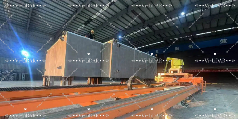
Vi-LiDAR: workpiece and trolleys from the client ” LB Tech.”
Conclusion
Manufacturing is entering an era of automation and AI-driven transformation. 3D Vision-guided pre-alignment technology is not just an upgrade—it’s a revolution in painting. By addressing long-standing challenges in industrial coating, these systems empower businesses to thrive in the digital age.
As enterprises adopt smart technologies, those who innovate today will define the future of industrial processing.


